Well Pump and Sump Pump Wire Sizing: Get It Right the First Time
Using the wrong electrical wire for your pumps is a fire hazard and can burn out the motor. You need the correct size to keep things safe and running.
We will cover how to find your pump’s amperage, choose the right wire gauge from common charts, and the critical steps for a safe hookup.
I’ve installed and repaired these systems for years, both at home and on the job. The rule is simple: never undersize your wire.
The Pump Wire Rule Book: Understanding Gauge, Amps, and Distance
Think of electrical wire like a garden hose for electricity. A skinny hose restricts water flow. A fat hose lets more water through easily. Wire gauge works the same way.
The American Wire Gauge (AWG) number tells you how thick the copper inside is. A smaller AWG number means a thicker, more capable wire. For example, a 12-gauge wire is thicker than a 14-gauge wire.
You need the right thickness for three reasons: the pump’s hunger for power, the system’s pressure, and how far it has to travel.
The Three Key Factors
You must know these three numbers before you look at a single spool of wire.
- Pump Amperage (Amp Draw): This is how much current the pump “drinks” when it’s running, especially at startup. Find this on the pump’s nameplate or manual. A pump that draws 10 amps needs a heavier wire than one that draws 5 amps.
- Voltage (120V vs. 240V): Most well pumps use 240 volts. Sump pumps often use 120 volts. Higher voltage systems can use a smaller wire gauge for the same power, which is why well pumps almost always use 240V. Using a 120V wire on a 240V pump is a surefire way to create a hazard.
- Distance from the Panel: This is the total length of wire from your breaker panel to the pump. Measure it. This distance is why simple charts often fail.
Voltage Drop: The Silent Pump Killer
Electricity loses pressure, called voltage, as it travels through wire. This is voltage drop. Over a long distance, a wire that’s too thin can cause such a big drop that your pump struggles, overheats, and burns out prematurely.
For a well pump hundreds of feet away, preventing voltage drop often dictates a thicker wire than the pump’s amperage alone would require — it’s non-negotiable, especially for well pump electrical systems where voltage drop can be an issue.
The Final Authority: The National Electrical Code (NEC)
Your local building codes are based on the NEC. This book isn’t a suggestion. It’s the law for safe electrical installation. It has tables that specify the minimum wire size based on amperage and other conditions. Your installation must comply.
Water Science Snippet
Voltage drop in a long wire is identical to water pressure drop in a long, narrow pipe. Push water through 50 feet of garden hose and you get good pressure. Push it through 500 feet of the same hose, and it just dribbles out. The resistance over the longer distance kills the pressure. A thicker wire (like a bigger pipe) reduces that resistance, delivering the power your pump needs to run properly.
What Gauge Wire for My Well Pump? (The Deep Dive)
Let’s get specific. For a residential home well pump is almost certainly a 240-volt submersible pump. Sump pumps are a different beast, usually 120V, and we’ll touch on that after.
This table gives you a solid starting point for common 240V submersible well pumps. It assumes standard conditions and includes a buffer for voltage drop on longer runs.
| Pump Motor (HP) | Typical Full-Load Amp Draw | Wire Gauge (Up to 100 ft) | Wire Gauge (100-200 ft) | Wire Gauge (200-300 ft) |
|---|---|---|---|---|
| 1/2 HP | 5-6 Amps | 14 AWG | 12 AWG | 10 AWG |
| 3/4 HP | 7-9 Amps | 14 AWG | 12 AWG | 10 AWG |
| 1 HP | 9-11 Amps | 12 AWG | 10 AWG | 8 AWG |
The rule is simple: longer distance requires thicker wire (a smaller AWG number). If your well is 250 feet from the house and you have a 1 HP pump, you’re likely looking at 8-gauge wire, even though the amp draw might seem okay for a thinner 10-gauge at shorter distances.
Direct Answer: What Size Electrical Wire Do I Need?
You need the wire size that meets three criteria: 1) It handles the pump’s amperage per NEC tables, 2) It keeps voltage drop below 3% for the total circuit length, and 3) It’s approved for its location (indoor, underground, etc.). For a typical 3/4 HP pump 150 feet away, 10-gauge direct burial cable is a very common and safe choice.
Wire Types: Romex vs. Direct Burial
You can’t use the same wire everywhere.
- Inside Your Home (Wet Location): From the breaker panel to the wall where the wire exits to the well, you typically use a cable like UF-B (Underground Feeder) or individual wires in conduit. Standard NM-B (Romex) is not for wet locations.
- To the Well (Direct Burial): For the buried run, you use a labeled direct burial cable like UF-B or USE-2. This cable is designed to be buried directly in the ground without conduit. For very long runs or rocky soil, pulling individual THWN wires through a buried conduit is the professional standard.
The DIY vs. Pro Verdict
Difficulty Rating: 9/10.
A homeowner can and should understand these specs. You need to know what the electrician is proposing. But the physical work of trenching, pulling heavy gauge wire hundreds of feet, making the sealed connection at the submersible pump, and tying into the main panel is licensed electrician territory (especially when it comes to electrical requirements like breaker size). The stakes are too high: personal safety, fire risk, and protecting a very expensive pump. My job is to know how deep to set the pump and what pressure tank to use. I always hire a pro for the final electrical hookup, and you should too.
What Gauge Wire for My Sump Pump? (The Basement Setup)
Most residential sump pumps are standard 120-volt units. They plug into a dedicated outlet right next to the pit. This isn’t just a suggestion, it’s the only safe and reliable way to power it. For best practices in sump pump pit installation, proper pit sizing, location, and drainage are essential. Following these guidelines helps ensure reliable operation and long-term safety.
You need to match the wire size to the pump’s amperage, which you’ll find on the pump’s nameplate. Here’s the simple rule I follow in my own basement and on service calls:
| Pump Amperage (A) | Minimum Wire Gauge (Copper, NM-B Romex) | Circuit Breaker Size |
| Up to 7.5A | 14-gauge | 15-amp |
| 7.6A to 12A | 12-gauge | 20-amp |
You never want to use a standard household extension cord for a sump pump, no matter what the gauge is. It’s a major fire hazard. Those cords can overheat, especially when buried in insulation or run through a damp crawl space. They also create a tripping point and an unreliable connection. If your pump isn’t near an outlet, the correct fix is to install a new, proper outlet instead of relying on dubious solutions that can even lead to sump pump failures.
The right way is to run a new, dedicated circuit from your main electrical panel. You’ll run the correct NM-B Romex (or UF cable if underground) to a weatherproof electrical box near the sump pit. Inside that box, you install a GFCI outlet. This circuit should have nothing else on it, so your pump doesn’t compete for power when it kicks on during a storm, especially for an outdoor sump pump.
So, what size electrical wire do you need for your sump pump installation? For nearly every standard 1/3 HP to 1/2 HP sump pump, a 12-gauge wire on a 20-amp breaker is the safe, code-compliant choice that gives you a margin for error. Beyond wire size, sump pump electrical circuit safety requirements typically call for a dedicated circuit with proper grounding and GFCI protection in damp locations. This helps prevent overloads and shocks while staying code-compliant. I use 12/2 Romex for my own setup because it handles the startup surge easily.
Code & Compliance Check
The National Electrical Code (NEC) is clear on this. Outlets in basements, crawl spaces, and within 6 feet of a sink or the sump pit itself require GFCI protection. This device can save your life by cutting power instantly if it detects a ground fault. The code also requires fixed appliances like sump pumps to be on a dedicated circuit. This prevents overloading and ensures the pump works when you need it most.
Tools, Materials, and Step-by-Step Connection Guide
Gather your tools and materials before you shut off any power. Here’s your checklist:
- Tools: Non-contact voltage tester, wire strippers, screwdrivers (flat and Phillips), hammer drill (for masonry walls), tape measure, level.
- Materials: Correct NM-B Romex (e.g., 12/2), electrical conduit (if required by local code or for physical protection), GFCI outlet, weatherproof “in-use” outlet cover, single-gang outdoor electrical box, correct amperage circuit breaker, wire nuts, cable staples, cable connectors.
Running a Sump Pump Circuit (High-Level Steps)
- Turn Off Main Power: Shut off the main breaker in your panel. Verify the power is off with your voltage tester.
- Install the New Breaker: Mount the new 20-amp breaker in an empty slot in the panel.
- Run the Cable: Route the Romex from the panel to the sump pit location. Staple it securely every 4.5 feet and within 12 inches of any box. Drill through studs as needed.
- Mount the Outlet Box: Secure the weatherproof electrical box to a stud or masonry wall near the pit.
- Make the Connections: At the outlet, connect the black (hot) wire to the brass “LINE” screw, the white (neutral) to the silver “LINE” screw, and the bare copper (ground) to the green ground screw. At the panel, connect the wire to the new breaker and the neutral/ground bars.
- Test the System: Restore power. Press the “TEST” button on the GFCI outlet. It should click and cut power. Reset it. Plug in your pump and test its operation.
For a Well Pump: A Pro’s Job
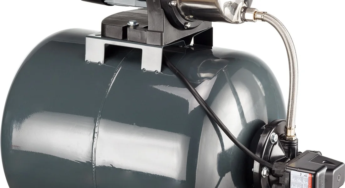
Well pump wiring is different and usually best left to a licensed electrician or well professional. It involves installing a weathertight disconnect box near the pressure tank, running rigid or PVC conduit from there to the well casing, and pulling individual THWN wires through it. The connections at the pressure switch and inside the well cap are precise. One mistake can fry a very expensive pump. My role as a homeowner stops at the pressure switch. Everything from the disconnect box to the pump in the well is a pro’s domain. Knowing the typical well pump wiring types and voltages helps explain the scope of the work. Most residential wells use single-phase 120/240V with rigid or PVC conduit, which is why a licensed pro handles the install.
When NOT to Try This
Call a licensed electrician immediately if:
- Your electrical panel has no open slots for a new breaker.
- The thought of working inside the live electrical panel makes you nervous.
- Your installation requires wiring any part of the submerged well pump.
- Local building codes require a licensed professional for permit and inspection.
Getting shocked or causing a fire isn’t worth the saved service fee. Be smart about your limits.
Keeping Your Pump Circuit Healthy and Safe
Choosing the right wire size is the first step. Keeping that circuit working safely for years is the next. Think of it like changing the oil in your car, it’s simple maintenance that prevents major failures.
System Maintenance Roadmap
Don’t wait for a flood or a dry well to check your system. A few minutes of routine checks can save you thousands in emergency repairs. Schedule a quick walk-around of your pump’s electrical components every season to catch small problems before they become big ones. Here is your simple checklist.
- Test GFCI Outlets Monthly. Press the “TEST” button. The outlet should click off. Press “RESET” to restore power. If it doesn’t trip, replace the GFCI immediately. I test mine when I check the smoke detectors.
- Listen for Pump Motor Strain. When the pump kicks on, it should sound like a confident hum. A loud groaning, screeching, or labored sound means the motor is struggling, often due to a failing capacitor or voltage issues from poor wiring.
- Ensure the Disconnect Box and Wiring are Dry and Rodent-Free. Open the outdoor disconnect box (with the power off at the main panel first). Look for moisture, insect nests, or signs of chewing. Rodents love to nest in warm boxes and chew on wire insulation.
- Check Pressure Switch Contacts for Arcing Annually. This is for well pumps. With the power OFF, remove the cover on the pressure switch. Look at the metal contact points. If they are blackened, pitted, or worn down, they are arcing. This creates resistance and heat, which can lead to pump failure.
Recommended Products
Using the right materials from the start makes everything safer and lasts longer. Always choose quality components designed for damp environments and continuous electrical load. Don’t cut corners here.
- Solid Copper Wire (Not Aluminum): For these pump circuits, always use solid copper THWN or THHN wire inside conduit. Aluminum wire is more prone to corrosion and loosening at connections, which causes dangerous heat buildup.
- High-Quality GFCI Outlets: Buy a name-brand GFCI from an electrical supply house or reputable home center. The cheap versions fail more often and can give you a false sense of security.
- Plastic Liquid-Tight Conduit for Damp Areas: Use this flexible, waterproof conduit for the final connection to the pump itself or in any wet location (like a sump crock). It seals out water better than standard flexible metal conduit.
- Surge Protectors for Well Pump Controls: Lightning strikes or power grid surges can fry your well pump’s control box in an instant. A whole-house surge protector is best, but a dedicated surge protector wired into the pump circuit is a good defense.
The “Red Flag” Troubleshooting Guide
When something goes wrong, your pump and wiring will give you clues. Ignoring these warning signs usually leads to a burned-out motor or an electrical fire. Here’s what to watch for: warning signs of sump pump failure.
- Pump Frequently Trips the Breaker. This points to two main issues: the wire is too small for the distance and load (causing overheating), or the pump motor itself is failing and drawing too much current (amps).
- Pump Hums But Doesn’t Start. This is a classic sign of voltage drop. The motor isn’t getting enough power to spin, often because of undersized wire, a bad connection, or a failed capacitor in the control box.
- Burning Smell from the Motor or Wiring. Shut the power off at the breaker immediately. This is a severe overload. You have insulation melting somewhere, either inside the motor or at a wire connection that has come loose.
- Water in the Electrical Junction Box. This is an immediate safety hazard. Power down the circuit. You have a leak or condensation issue that must be fixed before the pump is used again. All connections and conduit must be completely dry.
- Intermittent Operation. If the pump works sometimes and not others, suspect a failing pressure switch (for wells), a loose wire connection, or a breaker that is starting to fail and needs replacement.
Quick Answers
Can I use an extension cord for my sump pump in a pinch?
No, never. Even a heavy-duty extension cord is a major fire and shock hazard for a permanent appliance. It creates a high-resistance connection that can overheat. The only correct solution is to install a proper, dedicated outlet.
My well pump wire is already buried. How do I know if it’s the right size?
Find the wire size printed on the cable jacket where it enters your house or pressure switch box. Compare that number (like 12 AWG) to your pump’s amperage and the distance to the well using a reliable chart or the NEC. These are part of the electrical specs for your well pump, especially its amperage. Knowing the amperage helps you size the circuit and gauge long-run performance. If in doubt, have an electrician perform a voltage drop test under load.
Is aluminum wire ever okay for these pumps?
I do not recommend it. For pump circuits, always use solid copper wire. Aluminum is more prone to corrosion and loosening at connection points, which creates dangerous heat and is a common failure point I see on service calls.
What does “dedicated circuit” mean for my sump pump?
It means the outlet your pump plugs into is the only thing on that circuit breaker. This is a code requirement to prevent something else (like a freezer or worklight) from overloading the circuit and shutting off power to your pump right when you need it during a storm.
The wire gauge chart says 14 AWG, but my electrician is using 12 AWG. Why?
This is a sign of a good electrician. They are “upsizing” the wire to provide a safety margin, reduce voltage drop further, and future-proof the installation. A thicker wire than the absolute minimum is always a safer, more reliable choice and is perfectly compliant.
Getting Your Pump Wiring Right
Start every pump project by reading the amperage on the motor’s nameplate. Pair that number with a wire size chart for your run’s length, and always cross-reference your local electrical code.
Bob McArthur
Bob is a an HVAC and plumbing industry veteran. He has professionally helped homeowners resolve issues around water softeners, heaters and all things related to water systems and plumbing around their homes. His trusted advice has helped countless of his clients save time, money and effort in home water systems maintenance and he now here to help you and give you first hand actionable advice. In his spare time, Bob also reviews home water systems such as tankless heaters, water softeners etc and helps home owners make the best choice for their dwelling. He lives around the Detroit area and occasionally consults on residential and commercial projects. Feel free to reach out to him via the contact us form.